Home > Manuals > iQ Whole House Entertainment > IMA6 Amplifier > Installing the IMA6
Installing the IMA6
| Front of the IMA6 | ||
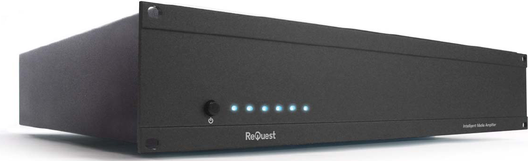 | ||
 | Front Power Button - Turns the amplifier on/off. Please note that there is no power indicator LED. | |
 | Active Zone Lights - A blue light will appear on any of the zone lights when the corresponding zone on the amplifier has been activated. | |
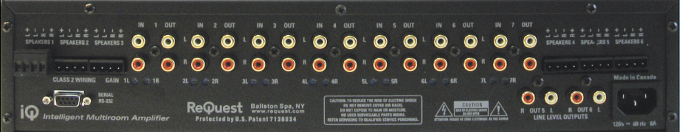
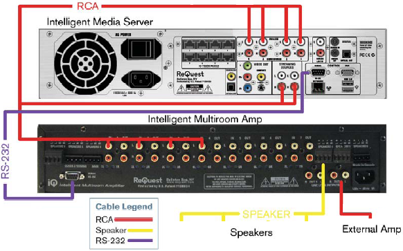
| Back of the IMA6 | ||
| ||
 | AC Power Connector - Connect to either 110 volt or 220 volt based on which power supply the amplifier uses. The power supply is not auto-detecting. | |
 | Serial - Used for connecting the amplifier to the IMS. This connection will allow the IMS to control the IMA6. No third party integration is supported. | |
 | Analog Audio Input - Analog audio input connectors for each source. Sources typically include hard drive, streaming radio and finetune sources from the IMS in additional to serial, IR and uncontrollable sources. You can input up to seven sources. | |
 | Analog Source Loop Output - Analog audio
output for the purpose of sending the source signals to a second amplifier, doubling the number of zones the amplifier can distribute to. If there is only one amplifier in the installation, these outputs are not used. | |
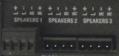 | Analog Phoenix Connector Output - Analog phoenix connector outputs to to connect speakers to the amplifier. There are up to six analog outputs available to source six zones. | |
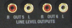 | Line Level Output - Line level outputs for the purpose of sending the zone output to a third party amplifier. This is typically used in home theaters and rooms or outside space that require more robust sound. | |
| Installation Instructions | ||
 | ||
| ||
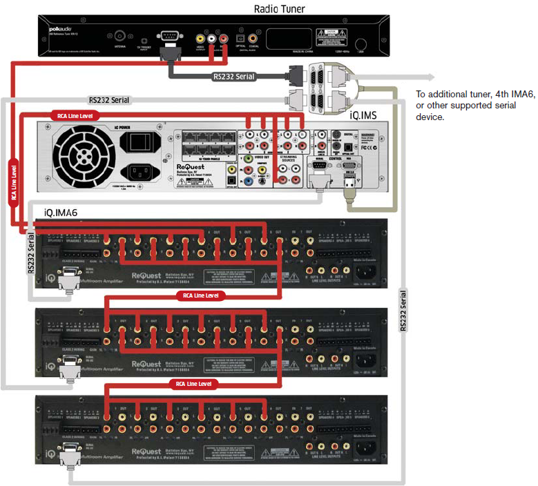 | ||
| Above is the suggested wiring guide for 3 IMA6s (18 Audio Zones). Setup is similar to the other configuration shown. Be sure to connect the Source Outputs of each IMA6 to the Source Inputs of the next IMA6 in line. The remaining Serial connection on your SCK4 can go to another tuner, another supported serial control device, or a fourth IMA6. |
See also